
Cheeky-Thomas
INDEPENDENT VESPA SPECIALIST

Swingarm Rebuilding.
This how-to is about replacing the engine mountings on the GT & GTS range (upto 2013 models although the only difference on the new models is the addition of extra spacers)
If you want to know if your mountings have gone, as the handling has become strange, or it feels like the rear wheel is loose but youve checked and its not, then do this quick test.
Start the bike off the stand, then hold the front brake firmly and give a brief blip of throttle, the bike should just squat the rear end down like a heavy pillion got on board, however if the mountings have failed it will twist or clonk to one side with a wiggle.

Heres the bike for the work, a 2005 GTS250ie but they are all the same so it doesnt really matter...

First job is the worst and thats getting the exhaust off including the manifold... and the nuts up front can be a pain, so soak overnight if you have the time, and try not break them off, if you think they are too tight get some serious heat on them first.

In this case they were so siezed they dragged the whole stud out as well, which is fine, ill just add new ones in at the end.
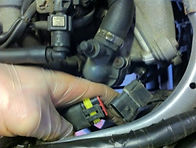
Now open the seat, remove the seat tub and follow the wire from the exhaust lambda sensor upto the connector, it will be a 4 wire like this, or a smaller 2 wire plug, makes no odds just unplug it..

Now remove the rear exhaust section completely and put aside somewhere safe, if its a original part then maybe its time for a wire brush up and a coat of black heat proof paint?
And also remove the manifold and lambda sensor taking care not to damage the wiring on the way out.


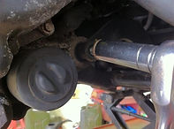
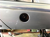
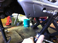
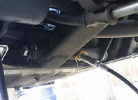
We need access to the vibration damper on the LH side, so remove the little floorboard end panel trim, early models its normal screws, later models have torx bits... either way remove it

Once the panels out of the way, undo and remove the circlip in the centre...

Spray the centre best possible with some WD40 or similar product to work its magic while we undo the other bits needed...

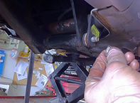
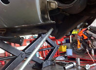
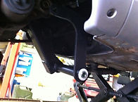
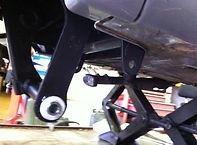
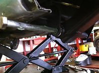
Right then now we need to support the bike to take the side to side rock out when the mountings are loose, they dont need to take any weight, just stop the bike leaning either way, personally i use 2 jacks, one each side... just use something to stop them marking the paintwork... you can use blocks of wood or whatever you fancy... they are just to stabilize the machine during the removal.
Now we get down to the proper serious bits... the unbolting... to start with just undo and remove the nuts, but leave the actual bolts in place...
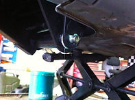
First up, undo and remove the engine to swingarm bolt, its a 17mm one side and a 15mm the other... it will be tight.
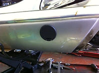
Now remove the plastic covers in the floorboard sections to access the swingarm to frame bolt.

And remove the nut.... its a 19mm bolt with a 18mm nut... and will also be tight.

Before you go any further, make sure the bikes standing on secure ground, wont need to be moved to get something etc, if you have someone available to just steady the bike then even better, nows the time to remove things serious!
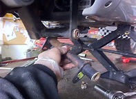
Back to the first bolt we undone, and knock it through... its often rusty so will need tapping out... as it comes out the engine *MAY* move a few mm's so dont panic....

And now go to the other bolt weve undone, and remove it... the engine and frame are now only connected via the shocks so be careful, dont sit on the bike etc... it wont go anyway but just be careful around it...

Now the swingarm is loose in the frame it can be pulled downwards slightly to give access to the centre pivot bolt...
Undo and remove the bolt... its 17mm both ends.
And now the bolt can be withdrawn...
The smaller front section of the swing arm is now loose and can be removed..

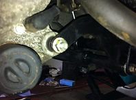
Now on the LH side near the vibration damper is a hidden spring connecting the swingarm to the body, use something to pull it downwards and off the swingarm, i use a cable tie in a loop but you can use a proper spring puller, piece of wire, coat hanger etc... whatever ya fancy.
With that undo, the swingarm is completely undone and just needs twisting and working out of the rubber damper, which is why we sprayed it with WD40 earlier on, and by now it should have done its stuff and will just work out...

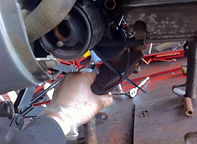
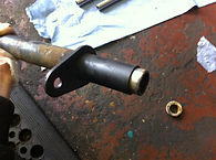
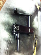
Now both parts of the swingarm are out and on the floor...

Its now obvious why this bike is "clonking" when ridden... look at the oval in the guide already visible..

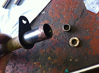
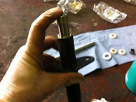
Remove the plastic guide to give access to the bearing...

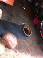
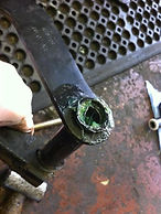
And now its clear why the guide was oval, this sides needle roller has completely disintergrated and fell apart allowing the shaft to move about unsupported, and will have been the cause of the engine knocking.

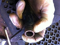
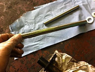
Now remove the centre chrome spacer tube, it should be nice and shiny, but in this cases its super rusty, and have grooves both ends where the bearings have worn into the shaft..

And now do the same removal on the opposite side...
At least this side has a bearing left, although its also rusted and far from in good condition...
Now using the old spacer tap the bearing and plastic spacer out...
Now that's one out, 3 more to go.
And heres the last one out... none look that good do they.
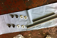
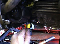
Now for the reconditioning... youll need these parts
This bit is optional, but if youve got time why not.... blast the brackets with some black paint while its off, it makes a better job in my opinion.

Right then, time to assemble the swingarm with the new bits... obviously clean the bits, especially where the bearings sit etc... and once done its time to knock in the new bearings, they wont be a tight fit so no need for a press or special tool, if you have one then of course you can use it... whatevers easiest for you.
I use a nylon hammer and tap them in flush (make sure the bearings in the right way round as they are handed... writing faces outwards)..

Once flush i tap them fully home using a socket the same size...

Once fitted, pack with as much grease as humanly possible... you can't add too much so be generous!
Then also grease up the new inner chrome tube...
And slide it into the new bearings, turning while doing so helps it get into the bearings easier... dont force it incase you damage a bearing... it should go easy, if not pull it out and try again

Thats one piece done, now do the same with the other, using the same process... dont forget the grease!!!!
Lots of grease...

Again greasing the tube...

And fitting as before..

Now fit the plastic end guides to all bearing/tube sections...
Now for getting it back together... like the famous haynes manual saying, refit is a reversal of removal!
Refit the larger arm into the rubber vibration damper unit...
Now get the smaller bracket into the bodywork, its handed so watch out which way you fit it... longer side goes towards the LH side...
Now grease the pivot bolt and get that fitted into the unit...
Line it up and shove it through both brackets.

And stick the nut on and tighten it up... again its 2 17mm nuts and the torque is listed as 33-41NM

Now you have to shove the whole unit back upwards into position, and line up the main frame bolt first... obviously grease the bolt up and slide that into place..
Now fit the nut, and tighten it up... its a 19mm bolt with a 18mm nut, tightening torque is listed as 76-83NM
A word of warning here, both sides where the bolt goes is a radiator hose, make sure you dont nip the hose with the bolt or nut as when you tighten it youll cut the pipe and have a sudden unwanted rush of coolant!
Once tightened up... refit the plastic covers

Now the worst one, the engine bolt... often youll find the engine has dropped slightly so youll need to lift the front a bit, and get the bolt started... again grease the bolt, and dont shove it all the way through!!
Refit the spacer in the centre of the engine mounts...
Now push the bolt through and put the nut on, then tighten the beauty up... its a 17mm bolt, 15mm nut and torque is listed as 64-72NM
Now refit the circlip on the mounting shaft through the vibration damper...
Refit the spring onto the swingarm, i use the same cable tie as when i removed it, and once fitted just cut if off...

Now refit the little side cover we removed earlier.

Time to refit the exhaust but first we will need to chuck a couple of new studs into the head first, so after a quick clean up with a M7 tap, 2 lovely new studs are coated in alloy paste and screwed into place... New self locking copper nuts are ready to refit the manifold.

Refit the exhaust, in this case its a non genuine leovince 4road, dont forget to plug the lambda sensor back in or you will get a EML show up on the dashboard.

So thats in back into place and job done...

Now ready for a test ride to enjoy the much improved handling.
Adding Grease Nipples.
Since doing this tutorial a few years ago, ive been adding a few steps during the rebuild, and while the units been apart ive been drilling and taping the main brackets and adding M6 grease nipples to allow filling the tubes with grease once assembled, and to also allow regreasing at service intervals, which has proved very worthwhile and when its done a lot of rusty water comes out and since then any machines with the nipples fitted havent required bearing replacements anymore... so definately worth the extra time and effort.

Heres the unit on the bench getting the grease nipple fitted.

Heres the positions ive chosen to use for the grease nipples once the units refitted to the machine... you need a flexible nozzle type gun but they are only about £10 for a cheap one.
Items in use during a service and working superbly indeed...